CAM & nesting
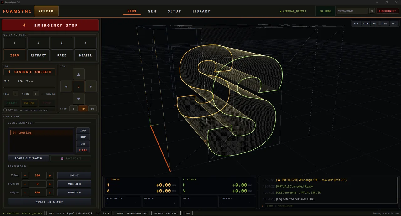
CAM is where part contours become the actual wire-tower toolpath. It lives in the RUN page’s CAM SCENE panel and the 3D viewport.
The CAM scene
Parts arrive in CAM from a generator (SEND TO CAM / → CAM), from the freehand Grid Sketch, from an SVG / DXF import, or from the library. The SCENE MANAGER lists everything currently on the block:
- ADD — add a part. DUP — duplicate the selected one. DEL — remove it. CLEAR — empty the scene.
- LOAD RIGHT (4-AXIS) — load the selected profile onto the right tower for an independent 4-axis cut.
- SAVE TO LIB — store the whole scene/block for later recall.
REPLACE / ADD / CANCEL
When you send parts from a generator and the CAM scene already has parts, FoamSync asks how to handle it:
- REPLACE — clear the scene and load only the new block.
- ADD — keep the existing parts and consolidate the new ones onto the same physical foam block (useful when auto-nest fills each block only partway).
- CANCEL — leave CAM as-is.
This prompt appears for every generator path, so you never silently overwrite or merge a scene.
Transforms
Position and orient parts with the TRANSFORM controls:
- X-Pos, Y-Offset, Height — place and size on the block.
- ROT 90° — rotate the part.
- MIRROR H / MIRROR V — mirror horizontally / vertically.
- SWAP L ↔ R (4-AXIS) — swap which tower cuts which profile on a tapered/asymmetric part.
Auto-nesting
Nesting packs parts onto standard foam blocks. The packer uses a union-footprint of the top and bottom profiles, so it nests 4-axis tilted sweeps correctly (not just the flat outline). Per-generator strategies exist — e.g. shelf-row stacking for dome/building parts and a pair-interlock packer for pipe shells (two half-shells in the footprint of one full circle) — to raise block utilisation. Re-nest any time with RE-NEST.
Inner contours — holes & pockets
Parts can carry inner cut-outs: wing spar slots, the holes you draw in Grid Sketch, openings in a wall. A hot wire can’t lift mid-cut, so FoamSync reaches each inner loop along a retraced bridge — it cuts in to the pocket along the nearest edge, cuts the loop, then retraces the same path back out. The only marks left on the finished face are a single fine slit + entry per pocket, instead of two. Parts with no inner loops produce the same path as before — the bridge logic only engages when there’s actually a pocket to reach.
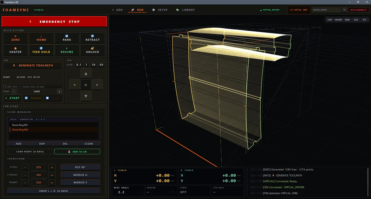
Generating the toolpath
Press GENERATE TOOLPATH. The 3D viewport fills with the dense wire path. The JOB status reads:
- IDLE — nothing generated yet.
- READY — a clean path; line/point counts and an ETA are shown.
- ⚠ DANGER — PRESS START TO REVIEW — the path generated but a check wants your attention (e.g. a steep wire angle). Review before cutting.
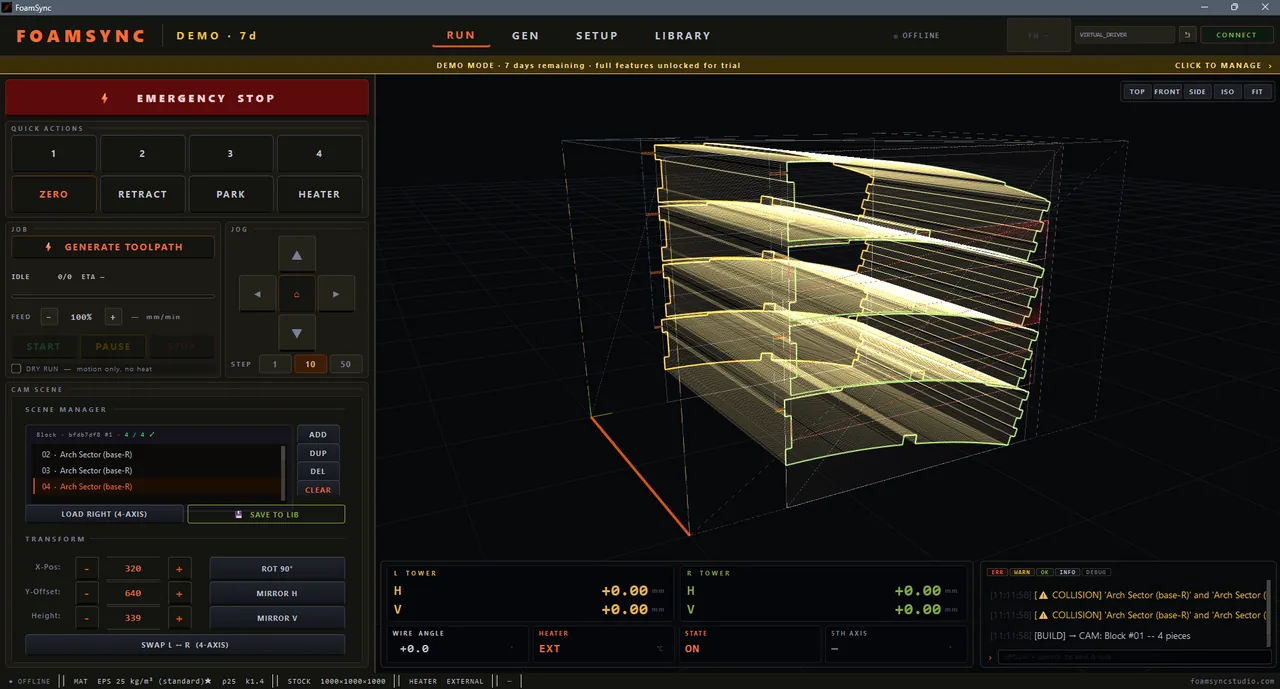
Collision check
If two parts overlap in the cut volume, FoamSync draws translucent red boxes in the 3D view marking the collision zones (bounding-box overlap detection). Resolve overlaps — move or re-nest parts — before cutting.
Wire-safety validation
Before a cut, FoamSync analyses the path against your max wire angle (SET → WIRE) and reports:
- Status — ✓ SAFE or a warning.
- Max / average wire angle, max strain, and the H / V components of the lean.
- Violations — counts of warnings (> limit), danger (> 1.5× limit) and critical (> 2× limit).
- Recommendations — plain-language next steps.
A SAFE result means the path stays within the wire’s safe lean for your span. Anything above the limit risks bowing or snapping the wire — adjust the part, the span, or the limit (only if your hardware genuinely allows it).
What’s next
Path ready and safe? Run the cut.